
By far, one of the most useful tools for talking about and understanding networks is the OSI Reference Model, maintained by the International Organization for Standardization (ISO). The acronym OSI stands for “Open Systems Interconnection.” The OSI model has been around for 30 years and still plays a viable part in understanding how networks communicate. In fact, it is now part of the networking vernacular. It is difficult, if not impossible, to discuss just about any aspect of networking without referring to the OSI Model.
The Seven Layers
The OSI model is a theoretical model that describes and standardizes the functions of network communication by breaking it into seven functional or logical layers:
7) Application layer
6) Presentation layer
5) Session layer
4) Transport layer
3) Network layer
2) Data link layer
1) Physical layer
Each layer provides for the layer above it and is attended to by the layer below it.
One way to memorize the names of the layers is to use a mnemonic device. For HTM staff, a good one is Please Do Not Throw Sausage Pizza Away. Each leading letter here represents one of the seven layers: P for the physical layer, D for the data link layer, and so on. If you ever plan on taking the CompTIA Network+ test, you’ll need to know the layers. So, once again, Please Do Not Throw Sausage Pizza Away!
Bottom-Up View
The physical layer, or Layer 1, is at the bottom of the stack. It serves as the direct connection to the wire, or to the airwaves in wireless networking. The physical layer defines the medium for the transfer of signal, whether using wires or not.
The data link layer, layer 2, provides the method for getting data on and off the media. It is the only layer that is divided into sublayers. One of the two sublayers is referred to as the media access control (MAC) layer. You may have heard of that one in terms of the MAC address. The MAC address is also called the hardware address or local area network (LAN) address. Since Ethernet resides at this layer, the Ethernet address is a MAC layer address. The Ethernet address is a 6-byte number written in hexadecimal, where each byte is delimited by a colon, such as 00:00:A1:FD:29:C4. Layer 2 is in charge of connecting to the LAN. Since bridges and switches make their packet-forwarding decisions based on the MAC address, they also operate at the data link layer.
The other sublayer is called the logical link control, or LLC. Again, Ethernet operates at this layer. The Ethernet LLC is the process for merging your network data with the LAN data traffic. The process is called carrier sense multiple access with collision detection, often abbreviated as CSMA/CD.
The Ethernet process listens to the media—looking to see if it senses someone else’s Ethernet carrier is present. If a carrier is present (that is, if another Ethernet node is talking), the protocol then is to wait for a random amount of time (called slot time) before checking the line again. It will keep checking and waiting until the line is clear and it can start to send out the bit stream via the physical layer.
While sending, it continues to listen to the line levels to sense if there is a collision with someone else’s data stream. If that happens, it will immediately stop sending data to send a jammer signal on the line instead. The jammer signal consists of 32 bits or 4 bytes of all digital 1’s, which all listening network nodes will sense as a carrier, effectively sending everyone back to restart the entire listening-then-transmitting process.
Again, the MAC is responsible for getting the data on and off the wire. The LLC is where the Ethernet transmit process functions—the software portion of media access—showing how to get on and off the wire. The LLC also accepts and inspects data packets, looking to see if any of them have your Ethernet address—called a unicast address.
The LLC is most often programmed to look for broadcasts as well. If the destination address is all 1’s (FF:FF:FF:FF:FF:FF), indicating a broadcast, it is to be accepted as well. A checksum routine tests whether the packet arrived intact by comparing the checksum it calculated with the checksum that was sent with the data. If the answer is yes, the information is extracted from the Ethernet envelope and passed along to the next software program.
The network layer, layer 3, refers to the wide area network (WAN). The network layer is mainly used to identify your location on the WAN as in IP addresses. Recall that a WAN is made up of two or more LANs. Layer 3 is where the IP or Internet Protocol resides and is why the IP address shows up here. Layer 3 is also where routers do their work, as they use the IP address to make their packet-forwarding decisions from WAN to WAN. Layer 3 is also the place where routers can exchange routing information. IP version 4 (IPv4) addresses are 4-byte numbers written in decimal, where each byte is delimited by a dot, such as 192.38.216.62.
[sidebar float=”right”]
TCP Port Number Ranges
TCP port number or addresses are 16-bit integers (2 bytes) written as one number in decimal notation, from 0 to 65535.
0–1023: These are “well known ports” assigned by the Internet Assigned Numbers Authority (IANA). Some examples: http (port 80), FTP data (20), FTP control (21), SMTP (25) POP3 (110), and DICOM (104).
1024–49151: These port numbers are requested from the IANA process and become “registered ports” with IANA. For example, DICOM has registered ports 1044 and 4006, and Googletalk has registered ports 19294, 19295, and 19302.
49152–65535: These numbers make up “unassigned” open space or free space: an area open to use and where cybercriminals often play…
Refer to www.iana.org for the current complete list of assigned and registered TCP port numbers.
[/sidebar]
The transport layer, layer 4, is where the Transmission Control Protocol (TCP) and User Datagram Protocol (UDP) reside. The transport layer is worried about how we are transferring the information. TCP and UDP operate as either a connection-oriented routine (TCP) or as a connectionless routine (UDP). TCP uses handshaking and counts the packets it transmits to verify delivery. This is why TCP is often referred to as a reliable data transfer method. By contrast, UDP is called unreliable, as it does not use handshaking, does not count packets, and makes no assurance of packet arrival.
A word of caution here: Keep in mind that the term TCP/IP really means two things. It refers to the two individual protocols of TCP and IP functioning at layer 4 and 3, respectively. The term “TCP/IP” is also the name of the Network Operating System—a suite of more than 200 individual apps or protocols. In general, written as TCP/IP, it most often refers to the whole enchilada—the entire Network Operating System that had its genesis in UNIX many moons ago. TCP and UDP—two of the many protocols in the TCP/IP network operating system—use TCP ports. TCP ports use a 2-byte number written in decimal notation ranging from 0 to 65,536 that helps to specify the TCP/IP protocol from the suite of protocols and processes within TCP/IP. (See the sidebar for more on TCP port numbers.)
The session layer, layer 5, defines the connection and how long to keep the connection going. It coordinates the dialog and overall connection for the length of the communication session. Networks need to keep the session alive and active while transferring all the packets needed to completely transfer a file, for example.
At the presentation layer, layer 6, networks need to define the messaging syntax, whether it is ASCII codes or other kinds of coding used for the information. That coding includes encryption, if any is being used, to transmit the message. The presentation layer is a busy place. In addition to establishing the data syntax, it is translating the data format as well. If I’m using a data format that I know my host doesn’t have, I can translate that at the presentation layer. Data compression can also happen here. While there is a lot going on in the presentation layer, its main job is to translate the data format for and from its host.
The application layer, layer 7, at the top of the OSI model, is where the application interface operates. Also known as the app socket, it is the final connection to the receiving application, like Microsoft Outlook for email, or to the ultimate destination of transmitted files.
Top-Down View
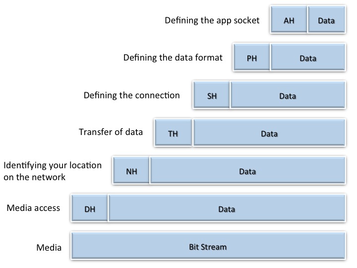
Figure 1. The OSI Model.
Now let’s look at the OSI model from top to bottom. Referring to Figure 1 above, the application layer takes the data from the corresponding app on your computer and effectively puts it in an envelope and adds an app layer header (AH) that defines how to connect with the app. You can think of this as annotations on the envelope, telling the recipient app layer how the data is to be given to the app at the top of the stack. The combination of the AH and its data portion is called the protocol data unit, or PDU.
The Application PDU is sent down the stack to the presentation layer. Unable to distinguish the AH from the payload, the presentation layer accepts the entire envelope as data, calling it a service data unit, or SDU. This Application SDU becomes the new payload and the presentation layer stuffs the Application SDU into the presentation layer’s PDU—or the presentation envelope—by adding the presentation header (PH) to send on as the presentation layer PDU. This is where the presentation header adds other information about the data inside. The presentation header also indicates if the data has been encrypted or compressed and sends it down to the session layer. The presentation header will always specify the syntax to ensure that the context of the information is well understood. This becomes the next PDU accepted as the presentation SDU in the payload of the session layer PDU at the layer below. And so it goes as the data travels down through the layers to the data link where Ethernet resides and runs its routine to arbitrate for access to the media and send the bit stream out.
Conclusion
As I said at the beginning of this article, the OSI Model has become part of the networking vernacular. To give just one example, the numeral 7 in the Health Level 7 (HL7) standard refers to layer 7, the application layer. So, recognizing how important the OSI model is, remember: Please Do Not Throw Sausage Pizza Away!
Jeff Kabachinski is the director of technical development for Aramark Healthcare Technologies in Charlotte, NC. For more information, contact [email protected].